The Problem With Replacing a Show System
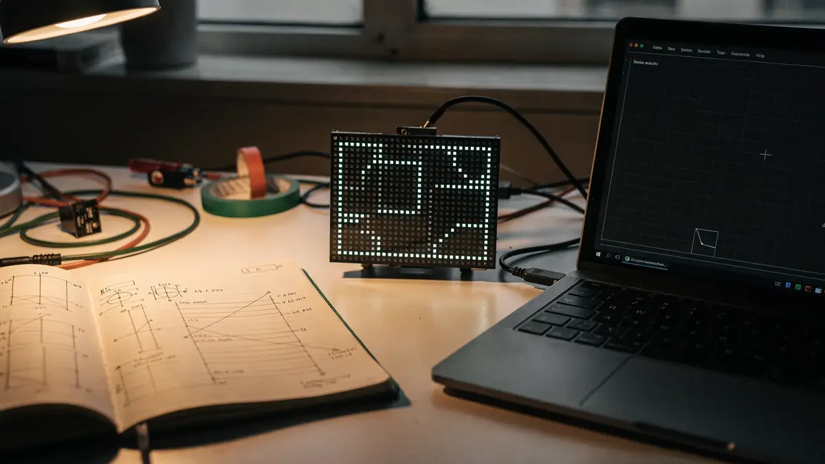
This came out of the same rebuild covered in Replacing TouchDesigner with a Custom Show Engine: an immersive venue's LED walls and projector, driven for years by a node-graph show tool. The visuals were the easy part to rebuild. The mapping wasn't.
Every pixel-mapped installation carries calibration data that took real time to get right — which physical LED corresponds to which pixel of the source image, in what order, at what brightness curve. None of it was documented outside the show file itself, and the show tool had no export for it. Getting it wrong meant a wall of garbage on opening night.
The question: how do you pull exact, provably-correct calibration data out of a system that was never built to give it up?
Treat It as a Black Box, Not a File to Read
The instinct is to go digging through the tool's project file or its scripting API for a "give me the mapping" answer. That search is a dead end more often than not — node graphs store the logic that produces a mapping, not the mapping itself, and reverse-engineering that logic by reading it is slow and error-prone.
The alternative: stop trying to read the system's mind. Feed it inputs you fully control, record exactly what comes out the other side, and solve for the mapping from the results. This is standard practice in camera and projector calibration — the same idea applies to any system that transforms a source image into physical output.
Generate Known Test Patterns
A set of calibration images: a gray-value ramp (for brightness response), solid red/green/blue (to catch channel swaps or bleed), horizontal and vertical gradients (to solve spatial position), and a few random "held-out" patterns kept aside purely to validate the final answer.
Feed Them In, One at a Time, With Proof of Receipt
Point the live system at each test image in turn. Stamp a unique marker color in the corner of every image and read it back before capturing — this is the detail that makes the whole method reliable. Async rendering pipelines cook frames on their own schedule; without a receipt check you risk capturing a stale or half-updated frame and never knowing it.
Capture the Real Output Buffer
Not a screenshot of a preview — the actual data the system is about to send downstream (DMX, sACN, a video frame, whatever the protocol is). Save each capture to disk, then restore the system's original state immediately. Nothing about the live show is permanently touched.
Solve for the Mapping Offline
With captures of gray steps, gradients, and solids in hand, the math is simple: the gradients reveal which source pixel maps to which output channel, the gray steps reveal the brightness transfer curve, and the solids confirm there's no channel crosstalk. The held-out random patterns get run back through the solved mapping and compared against reality — if that check fails, something in the model is wrong.
Why the Marker-Verification Step Matters Most
The single most important detail in this method isn't the math — it's the receipt check. Any live rendering system has its own timing: frames cook asynchronously, file loads aren't instant, and a naive "wait a fixed amount of time, then capture" approach will silently capture the wrong frame some fraction of the time. Those bad captures don't throw an error. They just quietly corrupt the calibration data.
Stamping a known marker color into each test image and confirming it's present before capturing turns an invisible race condition into a simple pass/fail check, per frame, for free. It's a small addition that's the difference between a calibration that's "probably right" and one that's provably exact.
This Generalizes Past LED Walls
Nothing about this method is specific to LEDs, TouchDesigner, or this particular venue. The pattern — known input, verified capture, offline solve, held-out validation — applies to any black-box system that transforms a source into physical or downstream output: projector edge-blending, camera color response, speaker array calibration, even legacy business systems where the only reliable way to learn the real behavior is to feed it controlled inputs and record what comes back.
What doesn't generalize is the plumbing — the specific node paths, the file-based bridge into the show tool's scripting console, the exact geometry of one venue's walls. Anyone applying this to their own rig rebuilds that part from scratch. The method is the reusable piece.